History
The development of the Neptus started in October 2004 to give support to the operations of Underwater Systems and Technology Laboratory USTL/LSTS in it's operations with autonomous vehicles. By then a REMUS like AUV (Autonomous Underwater Vehicle) and a ROV (Remoted Operated Vehicle) Phanton 500. Since then Neptus has growth with the laboratory being used to control not only AUVs and ROVs but also ASVs (Autonomous Surface Vehicle), UAVs (Unmanned Air Vehicle) and network of sensors.
USTL/LSTS Toolchain for Autonomous Vehicles
Neptus is part of the USTL/LSTS Toolchain for Autonomous Vehicles with IMC (Inter Module Communications) and DUNE (DUNE: Uniformed Navigational Environment). For more information on this toolchain go here.
Overview
Nowadays cooperative missions have great demand. Missions using heterogeneous vehicles to perform complex operations are demanding more complex infrastructures to support them. There are many issues to address when working with different kind of vehicles from different vendors, different capabilities and more important different interfaces to the end user. Interoperability is one of the most problematic issues. This is because there is no common acceptable interface. There are several interoperability efforts in several stages of development, but still not one widely accepted and used.
Let's for example think of a mission in what we use UAV (Unmanned Aerial Vehicles) with Piccolo Autopilot from Cloudcap Technology, one Woods Hole Oceanographic Institution REMUS model AUV (Autonomous Underwater Vehicle) and one LAUV AUV, from our Underwater Systems and Technology Laboratory. How to have one integrated interface to deal with these three different vehicles when they have three different interfaces?
Considering this type of operations we start developing Neptus. Neptus and aims to:
- Support multi-vehicle operations with a common interface;
- Support a mission lifecycle - planning, execution, review & analysis and dissemination;
- Easy integration of new vehicles and sensors;
- Integration of custom embedded message protocols;
- Allow customization of command and control user interface; and
- Concurrently operate multiple vehicles.
Neptus is a C4I (Command, Control, Communications, Computer and Intelligence) framework. It is build to support a mission lifecycle: planning, execution, review & analysis and dissemination.
The planning phase is the one that is for the preparation of a mission. For this, Neptus presents a virtual mission environment construction interface. In it a virtual representation of the mission site can be created. Geo-referenced images (with optional elevation map), geometric figures, 3D models and paths can be used to enrich the virtual representation. The virtual map edition interface can be seen in Fig. 2.
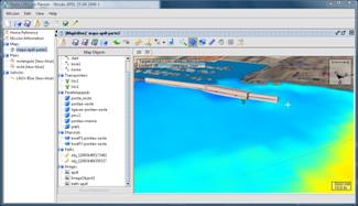
Fig. 2. Map representation
After we have the virtual representation of the mission site, the vehicles' mission plans have to be prepared. The planning of each mission plan is in the form of a graph and, for ease of use, can be drawn directly into the map previously created. As seen in Fig. 3, upon click on the map where we want a maneuver to be placed, a popup menu appears displaying the possible choices of maneuvers available for that particular vehicle.
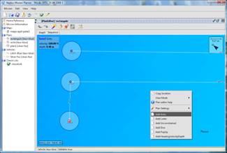
Fig. 3. Vehicle mission planning interface
Each vehicle has a configuration file in Neptus describing several capabilities that it can provide. This encompasses its feasible maneuvers, which communication protocols it supports and more graphical information on how to represent it in the virtual world. This information can be viewed and some modified through the interface like the one in Fig. 4. This way for each vehicle only the set of feasible maneuvers are presented to the user.
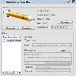
Fig. 4. Vehicle configuration interface
In the mission planning interface (Fig. 3), several plans can be created for several vehicles. At the end we get what we call a mission file which stores the maps, the vehicles' information and the several plans. All are stored in XML (eXtensible Markup Language) files.
After planning the mission we will execute it. For then on the focus is all on executing the mission. It is still possible to adjust or create more plans for the vehicles but for larger changes we can always open the mission planning interface. The main interface to the execution phase is depicted in Fig. 5. In it we can select and send plans to the vehicles and control and monitor the vehicle during the entire mission execution.
The operational console (Fig. 5) is connected to a communications interface that interfaces to several communication protocols. These protocols can encompass, for e.g., Ethernet, GSM or acoustics. Then all data received is redirected to a shared data environment and then the several console components can subscribe to this data and update themselves accordingly.
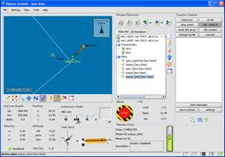
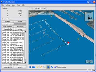
Fig. 5. Operational console
To improve the flexibility, the console layout can be edited allowing adding, removing and placing of the individual console components. In addition several monitor components can monitor specific messages to provide alarms (visual and vocal). Then the layout can be store in an XML file and then associated to vehicles. This makes also very easy to design new consoles and components allowing customization for each vehicle operational console.
To help the tactical communication between several human control units, a tactical channel is provided.
Upon conclusion of a mission, all collected data can be analyzed in the Mission Review & Analysis interface depicted in Fig. 6. This interface provides simple display with a history of logged data. There are a number of predefined graphics that are automatically generated upon opening a mission logs. Besides these predefined charts, with a couple of mouse clicks several others can be easily created.
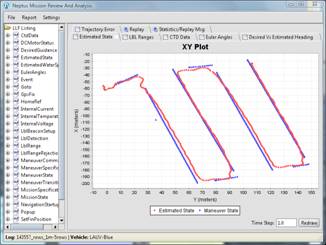
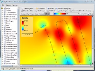
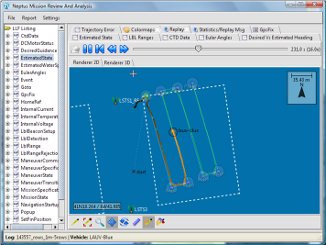
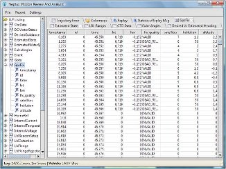
Fig. 6. Mission review and analysis interface
Another useful feature is the replay capability of the logged data. This comes in two flavors. One simpler that displays the evolution of the estimated state of the vehicle in a 2D or 3D renderer similar to the one on the operational console (see top left of Fig. 5). The other flavor of this replay capability is a heavier one that consists on taking the logged messages and sending them to the Neptus communications interface. Then, by opening the mission in an operational console, the evolution of the mission events can be followed. Each replay flavor capability gives access to the mission timeline and then the possibility to pause, advance, rewind, speed up or slow down the replay.
This tool also allows the generation of a report of the mission execution with the graphics and statistics in the form of a PDF document.
Another output of this tool is a partial automated elevation map generation for map integration (like the example depicted in Fig. 7).
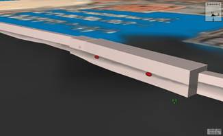
Fig. 7. Bathymetric profile in Leixões Harbor, Porto, Portugal (the two red buoys mark the surface of the water)
The dissemination interfaces is still in development. At this stage, real-time following of a mission can be achieved. On the mission site the vehicles positions and additional sensor data can be periodically be sent to a web server. This server can be consulted by a Web browser or a more dynamically option by Google Earth (Fig. 8) (Neptus Leaves - see on the above menu). Using this last option the several vehicles positions are updated and visually followed. In addition using the Time Span facility an animation of collected sensor data can be displayed.
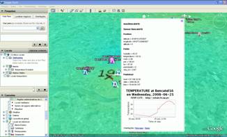
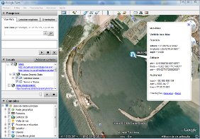
Fig. 8. Neptus Google Earth integration using data from wireless sensor networks deployment in Porto, Portugal, displaying temperature evolution as an animation or with popup dialogs for individual sensors (first image) and vehicle position and mission details (second image)
For UAVs we implemented a NATO Standardization Agreement that defines a standard interface of UAV control system (UCS) for NATO UAV interoperability, the STANAG 4586 version 2. This was created to promote UAV interoperability through the specification of common interfaces and architectures for UAV Control Systems (UCSs). The perceived value of UAVs in helping Joint Force Commanders (JFC) to meet a variety of theatre, operational and tactical objectives motivated these developments. By providing a common interface, it is possible to deploy the available UAVs and disseminate results at different command echelons. In spite of the orientation towards UAVs, there is nothing in the standard that prevents it from being used with other types of vehicles but is much focused on UAVs.
A STANAG 4586 enabled operational console is depicted in Fig. 11. 4586 defines one a message interface consisting of one embedded protocol. An embedded protocol means that messages are transmitted with a header in which some fields provide information on how to handle the message, and on how data is encoded or decoded. The messages are separated in several functional groups in which system messages, flight vehicle command and status messages, data link or payload messages are examples.
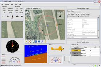
Fig. 11. STANAG 4586 ready console with UAV Lusitânia in loiter mode
To support 4586 a custom communications interface was developed to receive and send 4586 messages. Then several console components were created to support its message set and logic. Despite this, the planning of the missions is still the same as the normal planning interface. But in the case of STANAG 4686 the mission plan transformation is coded in one of the operational console components. In the UAV the ground station translates the Piccolo's commands to and from 4586 messages.